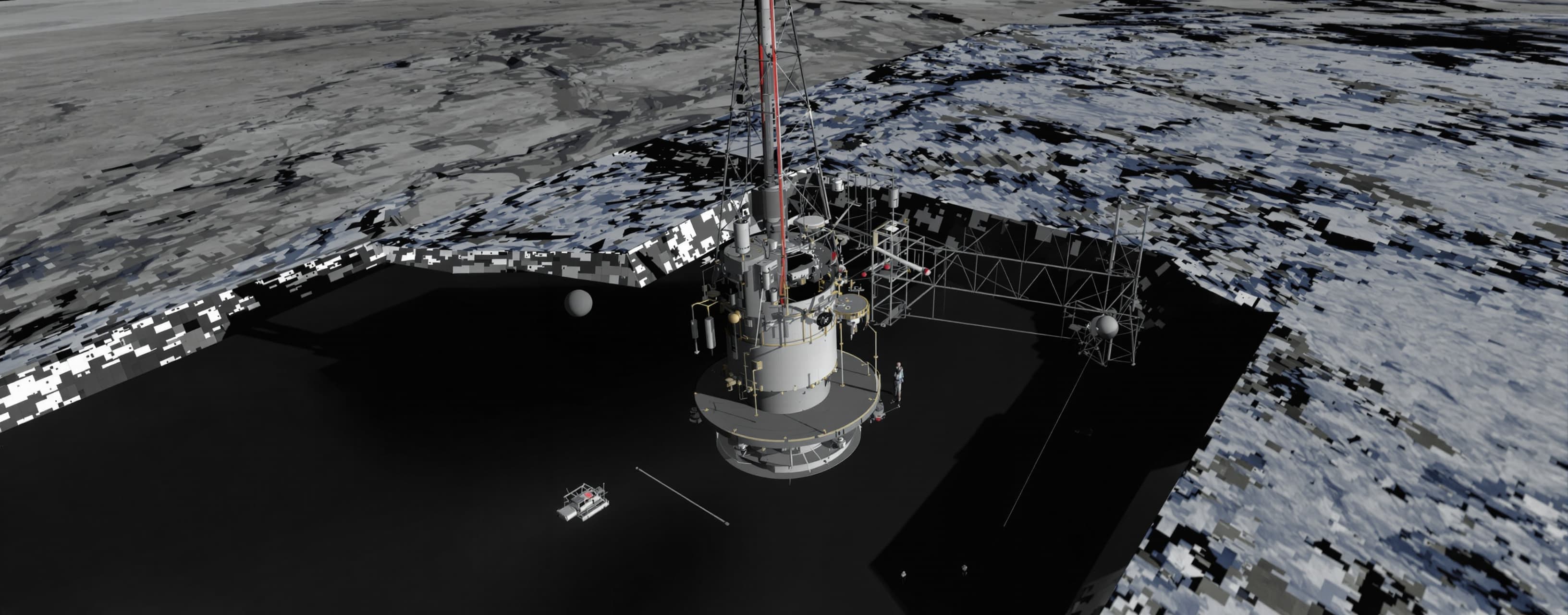
Generate a self-contained, minimal-UI single-file HTML/Three...
Prompt
Generate a self-contained, minimal-UI single-file HTML/Three.js interactive 3D model strictly based on the technical specifications and hierarchy of the ISA AM-300 surface propulsion installation below. Focus all output detail on accurate mechanical geometry, nozzle contours, radiators, and subsurface structures rather than web styling. Include OrbitControls, scene lighting, realistic procedural materials, toggleable ground transparency (to view subsurface structures), wireframe/solid toggle, and camera perspective presets. COORDINATE SYSTEM & SCALE: - Origin (0,0,0): Centre of thrust foundation at local Ceres ground level. - +Z: Outward / Upward (along engine thrust axis). - +X: Local East. +Y: Local North. - All dimensions in metres. Tower height: ~100 m. 1. FOUNDATION & ANCHORS (Z = -8 to 0 m): - Thrust Foundation: Annulus from Z = -8 m to Z = 0 m. Outside diameter (OD) 100 m, central circular opening 24 m diameter. Processed rock/regolith finish. - Anchor Ring: Radius 42 m, 12 equally spaced anchor tensioning heads. - Deep Anchors: 12 vertical bores (dia 1.2 m, internal tendon bundle dia 0.28 m) extending from ground level (Z = 0) down to Z = -300 m into bedrock. 2. PRIMARY LOAD FRAME & DECKS (Z = 2 to 36 m): - 12 inclined lattice buttresses arranged symmetrically at 30-degree intervals: * Lower attachment: Radius 42 m, Z = 2 m (anchored to foundation). * Upper attachment: Radius 14 m, Z = 36 m (supporting reaction shroud). * Profile: 3 m x 3 m square lattice truss with 4 longitudinal chords and diagonal cross-bracing every 4-5 m. Heavy articulated thrust bearings at both ends. - Lower Service Deck: Z = 12 m, circular platform, 42 m diameter. - Upper Service Deck: Z = 32 m, circular platform, 32 m diameter. 3. REACTION CHAMBER, THROAT & DIVERGENT NOZZLE (Z = 18 to 96 m): - Chamber Shroud: Z = 18 m to 48 m, maximum OD 20 m enclosing internal pressure vessel (internal diameter 10 m). - Throat: Z = 48 m to 52 m, internal diameter 8.4 m. - Divergent Nozzle: Z = 52 m to 96 m. Internal contour generated by revolving cubic Bézier curve (r, Z) around Z-axis: * P0 = (4.2, 52) * P1 = (4.2, 64) * P2 = (20.0, 88) * P3 = (24.0, 96) * Wall thickness envelope: 0.3 m to 0.6 m. Exterior ribbed with circumferential stiffeners and vertical regenerative cooling channels. - Exit Stiffening Rim: At Z = 96 m, outer diameter 50 to 54 m. - Outriggers: Instrument masts extending to Z = 104 m outside plume envelope. - Exhaust Plume: Upward-directed vacuum plume expanding within a 20-degree half-angle cone, luminous near throat/exit. 4. MAGNETIC CONFINEMENT RINGS (TOROIDAL CRYOSTATS): Three visible coil cryostats surrounding the chamber and nozzle: - Lower Interaction Ring: Centre at Z = 48 m, major radius R = 8.8 m, tube radius r = 1.2 m. - Intermediate Shaping Ring: Centre at Z = 70 m, major radius R = 13.8 m, tube radius r = 1.3 m. - Upper Trimming Ring: Centre at Z = 90 m, major radius R = 22.8 m, tube radius r = 1.4 m. - Pale metallic shell finish with insulated cryogenic feed pipes and quench lines. 5. HIGH-TEMPERATURE RADIATOR SYSTEM: - Main Panels: 12 high-temperature panels arranged in East and West banks (6 panels each): * Dimensions per panel: 24 m x 24 m x 0.25 m thickness. * East Bank: X = +95 m; West Bank: X = -95 m. * Panel Y-centres: Y = -75, -45, -15, +15, +45, +75 m. * Panel elevation: Centre at Z = 22 m. * Tilt angle: ~20 degrees from horizontal, emitting faces directed upward toward sky. * Visuals: Dark grey cold / glowing orange-red (1800 K) emitting face, insulated underside shields, large supply headers, deployment hinge struts. - Auxiliary Radiator Field (North of habitat): * High-temperature aux reactor radiators: ~800 m² panel area. * Low-temperature cryogenic plant radiators: ~2,000 m² panel area. 6. PROPELLANT FEED & WATER RESERVOIR: - High-Pressure Water Feeds: 8 insulated feed trunks (each 3 m diameter) entering the lower shroud. - Subsurface Water Reservoir: Buried cylinder (OD 160 m, depth 50 m) located in nearby subsurface. 7. ANTIMATTER (VCE) STORAGE VAULT (SUBSURFACE): - Vault Location: Subsurface centred at (X, Y) = (-90 m, -130 m). - Dimensions: Buried vertical cylinder, 12 m internal diameter, 18 m depth, with ground-level armored ejection hatch. - Ejection/Escape Capsule: 8 m diameter, 14 m length inside vault. - Cartridge Rack: 3 x 3 x 3 array of 27 isolated cylindrical fuel cartridges (each 1.4 m dia x 1.6 m length, spacing ~1.8-2.2 m). 8. CREW HABITAT COMPLEX & STORM SHELTER (SUBSURFACE): - Habitat Location: Subsurface centred at (X, Y, Z) = (0, 110, -35) m. - Habitat Pressure Hull: Horizontal cylinder along Y-axis, OD 4.6 m, straight length 8.4 m, hemispherical endcaps (total length 13 m). - Access Gallery: 2.4 m diameter pressurized tunnel connecting habitat to underground foundation galleries with two 90-degree radiation-attenuating bends. - Storm Shelter Capsule: Heavy radiation spherical capsule inside habitat centred at (0, 112, -35) m, outer diameter 3.94 m (internal clear diameter 2.4 m). 9. THREE.JS MODEL HIERARCHY & MATERIALS: - Scene Hierarchy: AM300_ROOT ├── TERRAIN_AND_FOUNDATION (Ground plane with opacity slider, annular foundation, 12 deep anchor bores) ├── THRUST_FRAME (12 lattice buttresses, lower & upper circular service decks) ├── ENGINE_CORE (Chroud, pressure chamber, throat, Bézier nozzle, cooling ribs, exit rim) ├── MAGNETIC_RINGS (Lower, mid, and upper cryostat tori) ├── RADIATOR_BANKS (12 tilted panels with emissive glow + aux fields) ├── FEED_SYSTEM (8 water trunks, subsurface reservoir) ├── STORAGE_VAULT (Ejection hatch, buried vault, escape pod, 27 fuel cells) ├── HABITAT_COMPLEX (Buried gallery tunnel, habitat cylinder, storm capsule sphere) └── EXHAUST_PLUME (Optional toggleable semi-transparent emissive exhaust cone) - Shading / Palette: * Trusses: Dark carbon composite with light ceramic joints. * Nozzle: Charcoal refractory exterior, interior throat glow. * Radiators: Incandescent orange-red faces with dark structural backing. * Cryostats: Brushed silver/titanium. * Subsurface mode: Ground cutaway or translucent ground plane so deep anchors, habitat, vault, and reservoir are clearly inspectable.
A system prompt was added to support web rendering
 OpenAI
Response not available
 Anthropic