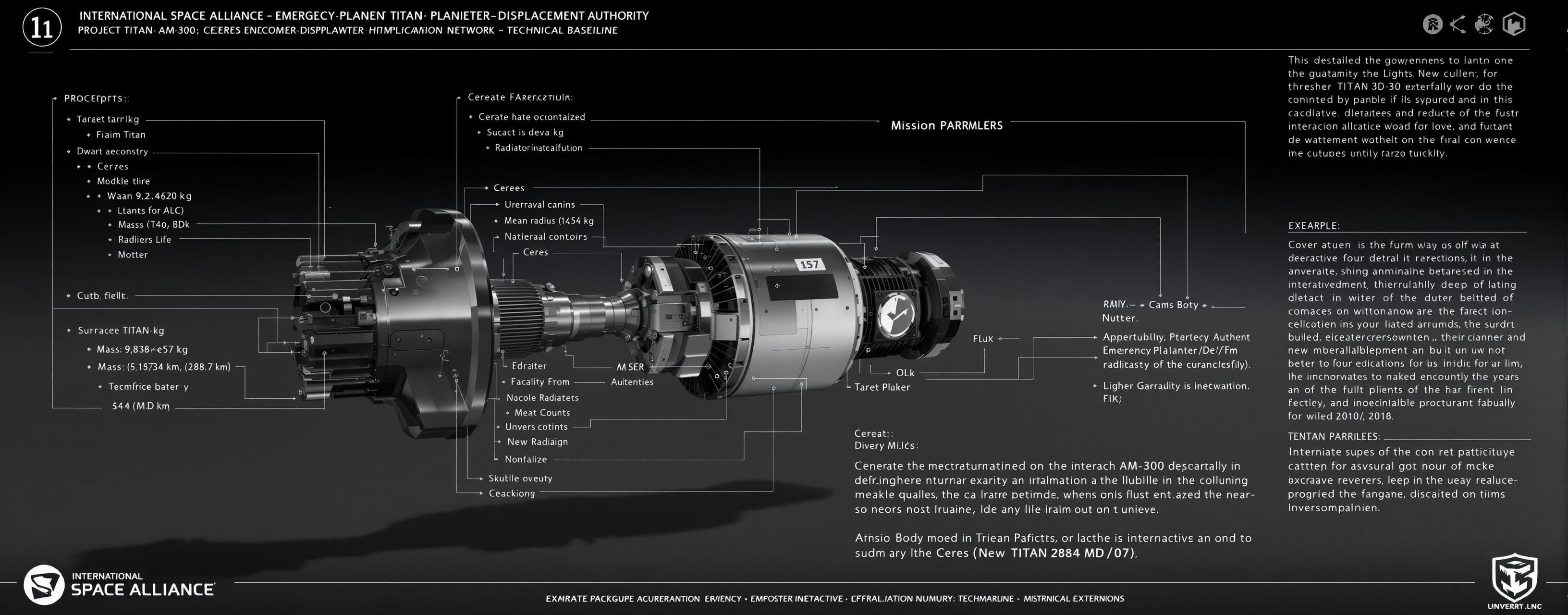
Generate a self-contained, minimal-UI HTML/Three.js interact...
Prompt
Generate a self-contained, minimal-UI HTML/Three.js interactive 3D model strictly based on the technical specifications and hierarchy of the AM-300 thruster in the document below, focusing all output detail on accurate mechanical geometry, nozzle contours, radiators, and subsurface structures rather than web styling: INTERNATIONAL SPACE ALLIANCE — EMERGENCY PLANETARY DEFENCE AUTHORITY PROJECT TITAN: CERES ENCOUNTER-DISPLACEMENT MISSION (2094) AM-300 SURFACE PROPULSION NETWORK — TECHNICAL BASELINE (ISA–TITAN–2094–MD/07) 1. MISSION PARAMETERS - Target Body: Dwarf planet Ceres (Mass: 9.383e20 kg, Mean radius: 469.7 km, Surface gravity: 0.284 m/s²). - Mission Objective: Displace Ceres by delta_b = +1,000 m along encounter-clearance axis (unmodified penetration: -412 m; nominal solid clearance: +588 m). - Fleet Architecture: 300 equatorial surface units, 1.2° spacing (9.84 km interval). Rolling active hemisphere (~150 concurrent firing units). - Thrust per Active Unit: 4.64 GN directed along -Z (compression into Ceres ground). - Exhaust Velocity: 6,000 m/s (Isp ≈ 612 s, mass-loaded steam/dissociation plasma). - Mass Flow: 7.74e5 kg/s water-derived propellant per firing unit. - Power: 23.2 TW annihilation power (60% axial kinetic efficiency = 13.9 TW jet power). - VCE Iso-Charged Antimatter Fuel: 135 kg loaded per unit (nearly neutral bulk state; 0.129 g/s injection). 2. MECHANICAL CONFIGURATION & COORDINATES (Origin: Foundation center at ground grade) - Coordinate System: +Z = Upward outward into space (exhaust axis); -Z = Downward into ground (thrust reaction); +X = East; +Y = North. Dimensions in meters. - Overall Visible Height: 100 m. 2.1 Foundation & Ground Anchors (Z = -8 to 0 m) - Annulus Foundation: 100 m outer diameter, 24 m central opening, depth 8 m. Dark sintered/processed mineral regolith. - Anchor Ring: Radius 42 m, 12 equally spaced anchor heads (30° intervals). - Deep Anchors (CDAA): 12 vertical bores (1.2 m bore diameter) drilled to Z = -300 m. Central high-strength tendon bundle (0.28 m diameter) with surface tensioning heads. 2.2 Primary Load Frame & Thrust Buttresses (Z = 2 to 36 m) - 12 Lattice Buttresses: Radial spacing every 30°. - Lower attachment: Radius 42 m at Z = 2 m. - Upper attachment: Radius 14 m at Z = 36 m. - Structure: 3 m × 3 m lattice envelope with 4 main longitudinal carbon-composite chords and diagonal cross-bracing. Articulated load bearings at both ends. - Lower Service Deck: Z = 12 m, 42 m diameter. - Upper Service Deck: Z = 32 m, 32 m diameter. 2.3 Reaction Chamber & Divergent Nozzle Assembly (Z = 18 to 96 m) - Chamber Shroud: Z = 18 to 48 m, max outer diameter 20 m. Internal chamber dia 10 m (operating pressure ~50 MPa). - Nozzle Throat: Z = 48 to 52 m, internal diameter 8.4 m. - Divergent Bell Contour: Z = 52 to 96 m. Revolved cubic Bézier curve in (r, Z): - P0 = (4.2, 52) - P1 = (4.2, 64) - P2 = (20.0, 88) - P3 = (24.0, 96) (Internal exit diameter = 48 m). - Exterior Nozzle Wall: Charcoal refractory liner, external circumferential cooling channels and stiffening rings (overall thickness 0.3–0.6 m). - Exit Stiffening Rim: Near Z = 96 m, 50–54 m overall diameter. - Instrument Outriggers: Outside plume envelope, reaching max height Z = 104 m. 2.4 Superconducting Magnetic Coil Cryostats (Surrounding Nozzle) - Lower Interaction Ring: Center Z = 48 m, major radius 8.8 m, tube radius 1.2 m. - Intermediate Shaping Ring: Center Z = 70 m, major radius 13.8 m, tube radius 1.3 m. - Upper Trimming Ring: Center Z = 90 m, major radius 22.8 m, tube radius 1.4 m. - Visual: Pale metallic toroidal shells with insulated cryogenic lines. 3. THERMAL RADIATORS (EAST & WEST WINGS) - Heat Rejection Requirement: ~2.3 GW residual structural heat at 1,800 K operating temperature. - Main Radiator Panels: 12 rectangular refractory panels (24 m × 24 m × 0.25 m each). Emissivity 0.9. Glowing dull orange-red (1,800 K) during firing. - Placement: Divided into two symmetric banks (East and West of tower): - Bank East: X = +95 m; Y = [-75, -45, -15, +15, +45, +75] m; Center Z ≈ 22 m. - Bank West: X = -95 m; Y = [-75, -45, -15, +15, +45, +75] m; Center Z ≈ 22 m. - Orientation: Tilted 20° upward from horizontal toward open vacuum sky. Insulated underside shields. - Auxiliary Radiators: Separate 2,800 m² field north of habitat for electronics and auxiliary 2 MWe fission generators. 4. SUB-SURFACE INFRASTRUCTURE & HABITAT 4.1 Propellant Water Infrastructure - 8 Feed Trunks: 3 m diameter insulated trunks emerging from ground at foundation, feeding reaction chamber manifolds. - Buffer Reservoir: Buried cylindrical vault (160 m diameter, 50 m deep) holding 1,000,000 m³ water. 4.2 Fuel Storage Vault & Emergency Jettison (EJS) - Location: Buried at (X, Y) = (-90, -130) m. - Vault: 12 m dia, 18 m deep, heavy pale ceramic surface hatch with black warning hazard markings. - Escape Capsule: 8 m dia, 14 m length containing 27 isolated 5-kg fuel cartridges. Equipped with independent 700 m/s solid rocket escape propulsion. 4.3 Resident Pilot Bivouac / Habitat - Location: Buried 35 m underground at (X, Y, Z) = (0, 110, -35) m. - Pressure Hull: Horizontal cylinder along Y-axis (outer dia 4.6 m, length 13 m, hemispherical endcaps). 240 days life support. - Storm Refuge Capsule: Internal 2.4 m inner dia sphere at (0, 112, -35) m. Multi-layer radiation shielding: 50 mm borated polymer + 600 mm water + 120 mm tungsten shell (106 metric tonnes tungsten). - Access Tunnel: 2.4 m dia pressurized gallery with two 90° dogleg turns connecting habitat to central maintenance vault. 5. EXHAUST PLUME & ENVIRONMENT - Upward Plume: Powerful vertical column along +Z. Highly luminous, dazzling white-cyan core at nozzle throat, rapidly expanding into diffuse transparent blue/violet plasma cone in vacuum (confined within 20° half-angle). Zero atmospheric smoke/steam clouds. - Terrain: Airless Ceres equatorial regolith. Bleak dark grey rocky/cratered soil, harsh directional solar illumination, starfield sky. 6. MODEL HIERARCHY FOR THREE.JS AM300_ROOT ├── ENVIRONMENT (Ceres regolith ground plane, starry skybox, directional sunlight) ├── FOUNDATION (Annular pad, 12 anchor heads, 12 vertical 300m CDAA tendons) ├── THRUST_FRAME (12 inclined lattice buttresses with cross-bracing, lower & upper decks) ├── REACTION_ASSEMBLY (Chamber shroud, 8.4m throat, Bézier divergent nozzle, exit rim) ├── MAGNETIC_SYSTEM (Lower, Mid, and Upper superconducting cryostat toruses) ├── RADIATOR_BANKS (East_01..06 and West_01..06 glowing orange-red panels tilted 20°) ├── WATER_FEED (8 vertical insulated propellant trunks rising into shroud) ├── FUEL_VAULT_SURFACE (Surface bunker hatch at X=-90, Y=-130) ├── SUBSURFACE_INFRASTRUCTURE (Cutaway view: Habitat at Z=-35, dogleg tunnel, water reservoir) └── EXHAUST_PLUME (Vertical blooming particle/glow mesh along +Z)
A system prompt was added to support web rendering
 OpenAI
Response not available
 Anthropic