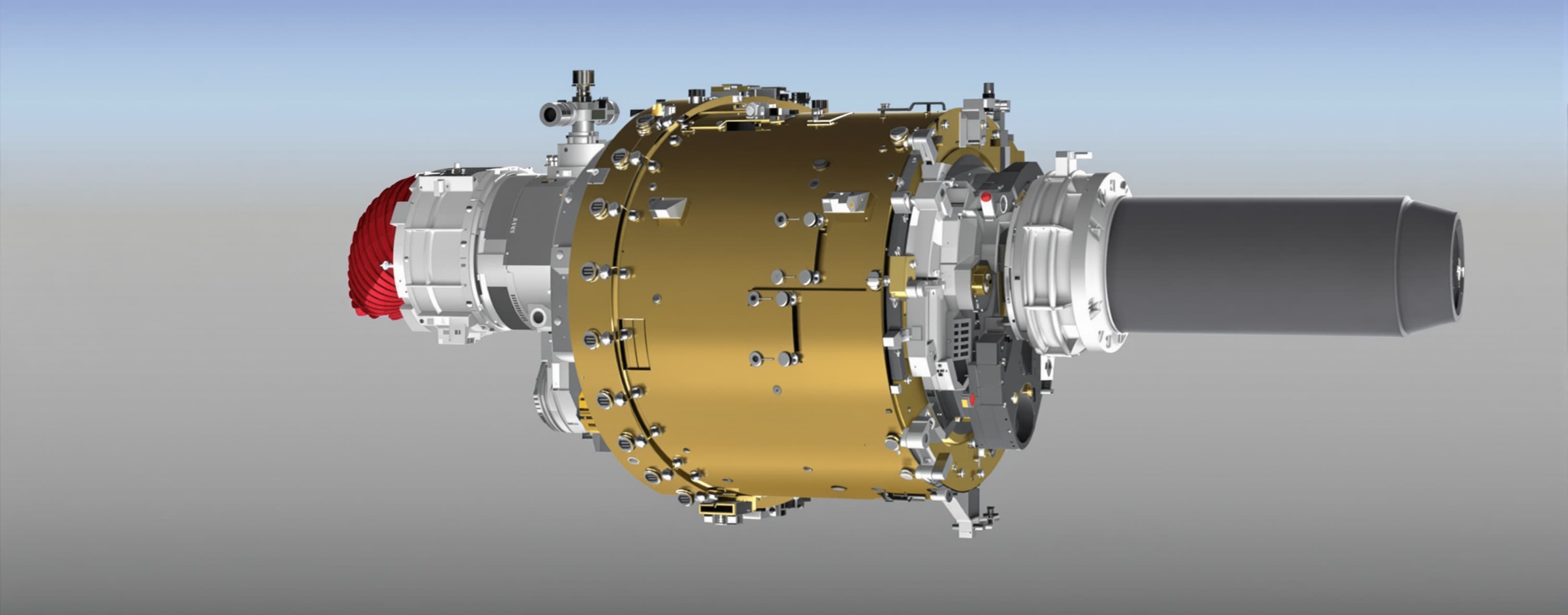
Create a pro level complex and highly detailed web based 3D ...
Prompt
Create a pro level complex and highly detailed web based 3D model in single HTML file, of a thruster using this documentation: ORBITAL ENGINEERING DIRECTORATE TECHNICAL DATA PACKAGE AM-300 HEAVY ORBITAL CORRECTION THRUSTER SYSTEM SYSTEM DESIGN BASELINE Document No: OED-TDP-AM300-SDB-001 Revision: E Classification: OED-BLACK Distribution: Program Office, Manufacturing, Integration, Operations Status: Approved Baseline — No Open Discrepancies --- 1. SCOPE This document establishes the approved design baseline for the AM-300 Heavy Orbital Correction Thruster System. It defines system architecture, performance parameters, subsystem specifications, interfaces, and compliance requirements. This document contains no operational narrative or historical analysis. --- 2. APPLICABLE DOCUMENTS Document ID Title ICD-008R EJS Corridor Interface Control Document VR-118 External Configuration, Sheets 1–2 2094-SW-117 Safety Waiver, as amended OED-STD-2074 Interplanetary Treaty Compliance Standard --- 3. SYSTEM OVERVIEW The AM-300 is a surface-emplaced matter/antimatter annihilation propulsion array designed to perform orbital correction of Ceres. The system consists of 300 thruster units arranged in twin belts at ±1.8°. During a continuous 21.0-day firing campaign, 150 units operate simultaneously, delivering a total orbital impulse sufficient to raise the semi-major axis by 1.000 km. --- 4. MISSION REQUIREMENTS Parameter Value Mission duration 21.0 days (1.8144 × 10⁶ s; 55.5 Ceres rotations) Orbital change target Δa = +1.000 km Required net impulse 2.0330 × 10¹⁶ N·s Delivered net impulse 2.0231 × 10¹⁶ N·s Shortfall 0.29% Terminal throttle reserve +1.48% Orbital efficiency 0.0998 --- 5. FLEET ARCHITECTURE Parameter Value Total units 300 Concurrent firing units 150 Belt configuration Twin belts, ±1.8° Continuous fleet thrust 11.174 GN Total handoff events 33,300 Handoff time skew ≤ 380 as Cumulative handoff impulse residual ≤ 9.4 × 10⁻⁴ N·s Exclusion zone — primary 5 km Exclusion zone — secondary 500 m --- 6. UNIT DESIGN PARAMETERS Parameter Value Thrust per unit 74.49 MN Exhaust velocity 150 km/s Propellant mass flow 496.58 kg/s Annihilation power 13.371 TW Exhaust kinetic power 5.587 TW Plume radiant power 2.67 TW RPHE capture power 4.60 TW RPHE capture fraction 92.6% of 4.97 TW input Parasitic load 0.46 TW Neutrino loss 0.05 TW Throttle envelope 20–120.8% nominal --- 7. SUBSYSTEM DESIGN 7.1 Antimatter Core Parameter Value Antimatter inventory 135 kg H̄/H Total energy content 1.21332 × 10¹⁹ J TNT equivalence 2.90 Gt Solid H₂ billet geometry Ø0.80 × 1.56 m Solid H₂ density 86 kg/m³ Beam injection system BF-12 Beam current 12 × 594 A Beam energy 1.2 keV Beam velocity 4.79 × 10⁵ m/s 7.2 Reaction Chamber Parameter Value Chamber material Dual W-25Re Wall radiation length 128 X₀ Ice-curtain capture fraction 96.3% PGCC operating pressure 81 bar PGCC operating temperature 15,000 K 7.3 Power Conversion Parameter Value EAC configuration 3 × 260 kV × 4.62 MA EAC directed power 3.17 TW MNA diameter Ø5.6 m MNA axial efficiency 96.5% RSERR capacity 206 GW 7.4 Power and Thermal Parameter Value CPEEC peak power 36.7 GW MDPB rating 12 kV / 16 × 192 kA SMES capacity 206 GJ SMES discharge rate 25.75 GW for 8 s Primary coolant ⁷Li Coolant mass flow 32,800 kg/s Li loop firing load 89 GW at ΔT 649 K Standby fin fan capacity 1.49 MW Standby fin fan safety factor 1.38 7.5 Foundation and Load Path Parameter Value Thrust line height above pad +6.00 m Overturning moment 447 MN·m Pad couple load ±16.55 MN Pad bond safety factor 2.69 CDAA diameter — inner Ø1.4 m CDAA diameter — outer Ø1.9 m CDAA depth 300 m CDAA qualified lateral bearing pressure 0.36 MPa CDAA lateral capacity 151.2 MN Lateral safety factor 2.03 — governing CDAA axial capacity 181 MN Vertical gravity load 1.37 MN Pad bond total capacity 12 × 44.6 MN = 535 MN Pad bond role Secondary shear path SOD load 30 MN 7.6 Safety Systems Parameter Value Beam abort response time < 200 ns PEDC energy dissipation 57 GJ in 8 s Emergency Jettison System Δv 410 m/s EJS elevation 45° EJS impact surface arc ≈ 993 km EJS sub-escape margin 20.6% EJS canister kinetic energy 10.1 GJ EJS solid motor class 18 GJ --- 8. MASS PROPERTIES AND LOGISTICS Parameter Value Total system mass 4,900 t Lift 1 2,600 t Lift 2 2,300 t Emplacement critical path 13.0 days (312 h) --- 9. PERFORMANCE BUDGETS 9.1 Unit Energy Budget Component Power (TW) Annihilation 13.371 Exhaust kinetic 5.587 Plume radiant 2.67 RPHE capture 4.60 Parasitic 0.46 Neutrino loss 0.05 Total 13.37 Closure residual: 0.0% 9.2 Impulse Budget Parameter Value Ideal impulse 2.0289 × 10¹⁶ N·s Loss budget +0.20% Required impulse 2.0330 × 10¹⁶ N·s Delivered net impulse 2.0231 × 10¹⁶ N·s Shortfall 0.29% Reserve +1.48% 9.3 Orbital Energy Budget Parameter Value Orbital energy change 3.633 × 10²⁰ J Orbital efficiency 0.0998 --- 10. RELIABILITY AND MAINTAINABILITY Parameter Value Unit MTBF — derated 6.3 × 10⁶ h Unit mission failure probability 8 × 10⁻⁵ Expected fleet failures during mission 0.024 Maintenance coverage Four-loss margin --- 11. COMPLIANCE Requirement Status Interplanetary Treaty 2074, Section 88, Para. 3 Compliant Safety Waiver 2094-SW-117, as amended Compliant EJS impact trajectory Sub-escape, surface arc ≥ 940 km Exclusion zones Per ICD-008R --- 12. APPROVAL Role Name Ceres Division R. Okafor Principal Stress M. Lindqvist Directorate Chief Dr. A. R. Venkatesh END OF DOCUMENT — OED-TDP-AM300-SDB-001 REV. E
A system prompt was added to support web rendering
 OpenAI
Response not available
 Anthropic